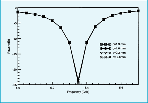
Fig 8 Simulated return loss of patch with change in ‘c’ dimension
| 362 | IETE TECHNICAL REVIEW, Vol 23, No 6, 2006 |

Fig 8 Simulated return loss of patch with change in ‘c’ dimension

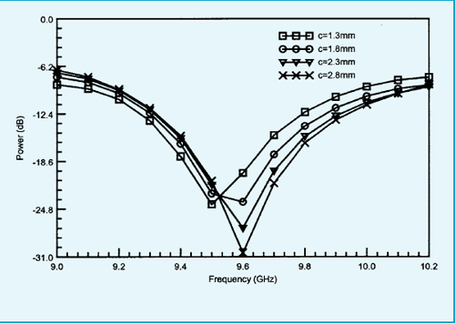
Fig 9 Simulated return loss of slot with change in ‘c’ dimension
Based on the dimension of the single radiating
element at C-band and X-band and the corporate
feedlines for both geometry a 2×2 array antenna is
fabricated and assembled. The fabricated antenna is
shown in Fig 10. The radiation pattern of the antenna is
measured at Anechoic Chamber Space Applications
Centre Ahmedabad. |
From measured results shown in
Fig 11 it is observed that return loss bandwidth for the
array is less than the bandwidth of single element. Fig
12 and Fig 13 show the radiation pattern of the patch
array and slot array respectively. Simulated gain of
patch array is 13.7 dBi at center frequency 5.35 GHz simulated gain of slot array is 11.0 dBi at center
frequency 9.6 GHz. |